Save settings and logs in a MCU internal flash

Saving settings and logs is necessary in a vast majority of modern devices. When we talk about a large system based on Linux and having, say, a SD card, there are no problems with solving such tasks. However, if your device is a microcontroller, then this task is not trivial. One solution is to use raw data placed in an external EEPROM for settings. However, this approach is much less convenient than a file system. Also it is not well suited for logging tasks. In this article, I’ll tell how you can organize convenient storage of settings and logs as files in the internal flash memory of the microcontroller.
A trivial read-only file-system
Let’s start with the very concept of a file system. When we think about the file system, we immediately get the feeling of something huge and therefore having a heavy overhead. Yes, there is an overhead, because for the description of files, at least their names or identifiers, you need memory. Yes, there is a problem with a rather large overhead when using universal file systems. The desire to make universal filesystems less resource-intensive led to the creation of littleFS , but even it requires 10kb (RAM + ROM), which may be too much for the microcontroller. After all, maybe you only need to store a few parameters.
Let’s figure out if it’s possible to reduce the overhead by limiting the functionality.
Of course it is! Because a file is just a named sequence of ordered data. Let’s put our parameters into a bytes array, give this array a name, and in fact, we get a file. Now let’s make some data files, pack them in CPIO format and put this archive in our firmware, while keeping the address of the beginning of the archive.
This can be done very simply. We need an assembly file in which binary data is placed in a special section
.section .rodata.embox.initfs.incbin CONFIG_ROOTFS_IMAGE
And by adding a linker script
SECTIONS { .rodata.embox.initfs: { _initfs_start = .; *(.rodata.embox.initfs) _initfs_end = .; }}
Now we can use these files! Labels and other metadata are available. Our filesystem is packaged in a simple cpio format that requires almost no overhead for parsing functions. Actually, in Embox this filesystem is called ‘initfs’. It is a fully functioning read-only file system in which both files and folders are available.
File in this FS is represented with its name and the address of the beginning of the data (and of course the data itself, which is just a byte array). Similarly, you can represent the file as a C-array and include it in the project during compilation. This method is widely used for example when creating websites based on LwIP. We talked about the advantages of Embox when creating websites in the article “Design web-site on Linux and running on a STM32 MCU”.
As a result, the proposed cpio-based approach has more or less the same overhead as the byte array implementation, and they both are more efficient compared to littleFS. It is no surprise that after all we’ve created an even more specialized solution than littleFS.
Common information about File System
Now let’s talk about some general principles of file systems. After all, when we talk about littleFS, we mean the type of the file system and the driver for this type. And in order to work with files, you need a few more concepts. For example, an inode describing an open file. Which should at least have methods for reading and writing the file.
We will consider only a few types of objects that are difficult to do without. Let’s start with the file descriptors. There are two types of file descriptions. The first the descriptor of the file specifies how the file is stored on the medium. It is called ‘inode’ . Note that the file name is not stored in the inode itself (because it’s not needed), but it’s stored in the file entry in the parent directory (directory entry (dentry)). ‘dentry’ stores the name of the file and a link to its inode, this information is needed to find the file in the file system.
The second file descriptor is the open file descriptor, represented as an index descriptor. This descriptor is obtained with the standard POSIX open () call . Note that the FILE object retrieved using fopen () is not a file descriptor, it is a stream descriptor, although in many ways the are related to each other. The index descriptor for the file must contain at least the current position at which it is being read or written and a reference to its inode.
A file system type determines the format in which metadata and data are stored in that file system. A file system driver is an implementation of functions for working with the file system type format. For example, the mentioned littleFS and initfs (in Embox) are file system drivers.
Another important object is the file system descriptor (superblock). It stores information about methods for working with the file system and its state (for example, related block device).
initFS driver
Let’s go back to the main topic, a file system inside a microcontroller. We have already realized that it is possible to create a convenient read-only file system with very little overhead. We lack quite a bit to work through the usual open / read / write / close, . For example, we need our driver to have some kind of API. Let’s take a look at some of the driver functions in Embox to see what this API can look like.
Here we define the driver itself. It has a file system name and a superblock fill function. The driver may also have the function of formatting the block device in the file system format and clearing the superblock, but we have a read-only file system and this is definitely not required.
The function of superblock filling
We fill in several pointers to functions for working with the file system in it. Also allocate an instance of the inode structure for this file system. Allocation is necessary because any file system has a mount point, which is also a file, or rather a directory.
The create () function creates a new inode on the file system, in our case it just returns a permissions error. We will need a couple of functions for operations with inode: lookup() function for searching by name in a given folder and iterate() — a function for iterating over inodes in a folder.
In fact, if you only need open/read/write/close, then you could work without iterate(). it is used in readdir(), but for the beauty of the implementation (and universality of course), the open () function is better expressed through readdir().
So the iterate () function gets a pointer to a new inode and a pointer to a name. This data must be filled in if there is another file in the folder. The input parameters are the inode of a parent directory and directory context. The directory context should contain data identifying the current file that is being read from the directory. Initially, the context is empty (0), and if a file is found, iterate() fills it in accordance with the file read, so that the next time it is called, it will search for the next file.
The lookup () function looks for a file with the specified name in the directory and, if found, returns a pointer to a new inode.
Among the superblock functions, open_idesc is interesting. For regular files it must allocate an idesc object, the file index descriptor itself on which read/write operations will occur. The inode that describes the file on disk is already full using the lookup function.
It remains for us to consider only the functions for working with read/write files. write () will be empty and just return an error. The read () function is quite simple
It just rearranges the current cursor and copies the data to a buffer.
File System
Now that we have the driver for our filesystem, let’s see what it does and estimate the overhead. On the screenshot below you can see it live in emulator:
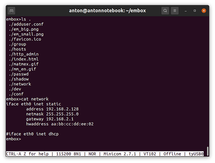
We can work with data located inside our image as with regular files. ‘ls’ command prints out files in the file system and ‘cat’ command prints data content itself, as you would expect.
How much does it cost? That is, how many resources are required for such convenience. It turns out that it’s not that big. I used STM32F4-discovery and I compared images with and without a file system, it turned out to be on text + rodata (that is, the code and constants, including the files themselves) need about 8 kB. That being said, I didn’t even turn on optimization for size. For RAM, it took about 700 bytes. Where do they come from? We need a superblock object, and an inode for every mounted filesystem. We need dentry objects including an inode for every open folder and file. need idesc for every open file etc.
Probably someone will say that a few KB for a read-only file system for a microcontroller is a lot. But you need to take into account that I was evaluating the entire subsystem, and together with the website files that took a couple of kilobytes. And adding another driver will require much less resources (if it is simple, of course).
DumbFS
Let’s develop a driver that can work in the internal flash memory of the microcontroller. A driver for storing settings and log files can be very simple. For example, we do not need to store file attributes, we can do it without directories, we can even say that only 3 files are needed there, because at the design stage, we can determine which files are needed and we can set their maximum size. The maximum size for a file can be useful, because we can immediately format our storage device to the specified characteristics, having reserved both the number of dentry (entries in directories) and space for each file.
Thus, our superblock can look like this
The first two bytes are just the filesystem ID to verify that our storage device is formatted properly. Next comes the file counter, in case we do not want to immediately format all the files, but still be able to create as in a real file system. Next comes the maximum number of these files. Both parameters are 1 byte in size, you hardly need to store more than 255 files on such a file system. Then comes the maximum file length. And then a couple of optional parameters. free_space is free unallocated space, although it can be calculated via inode_count. And buff_bk is used to define buffering. It is useful because an entire block must be erased in the internal flash memory before recording. This parameter can also be calculated and does not need to be stored on the device.
Further we can immediately place entries for the root directory, we have only one, so the data for it (dentries) can be located immediately after the superblock
It’s simple, the first parameter is the file name. The second is the offset of the start of the data in the storage device. The third is the current length. And the fourth optional flags or file attributes.
Let’s look at some of the driver’s functions
The suberblock filling function is similar to initfs: we also install the operation handlers, but since we have a real file system, we need to read the superblock data from the device and also fill the inode for the root folder.
The iterate () and lookup () functions are also similar to initfs, the only difference is in the dentry representation format.
Since we have added the ability to write, we need to implement, for example, the itruncate () function that changes the current file size.
Everything else is simple too, read the dentry for the file, change the current length and write.
The most interesting function of course is write(). The read() funcion is just copying from a specific address (well, or reading a block and copying, if the flash is still external), but writing is known to be a rather complicated operation. Moreover, you can only write down the block that was previously erased. That is, in order to write a block of data, you need to save (cache) the block, and instead of the old data, write new ones, erase the original block and write it with the new data.
We first clear the cache, then copy the data from the block that will not be changed to this cache, then write the new data, and copy the remaining unchanged data from the old block. Finally, the data from the cache is transferred back to the block, before that it is of course erased.
Why erase the cache? After all, this is usually just an array of data in RAM the size of the block. But in some microcontrollers, there is a lot of flash memory, but RAM is restricted. The STM32F4-discovery for example has 1024 KB flash. Among them, there are 4 blocks of 16kB each that could be used for our needs. But at the same time, there is only 128 + 64kB of RAM. And there is not always enough memory to allocate 16 KB of RAM. Then the second 16KB block can be used for caching.
Our file system is almost complete. Now we only need to learn how to write in the correct blocks of the internal flash. That is, you need to allocate several blocks of memory and turn them into a block device. Let’s tell the linker to reserve the appropriate memory.
SECTIONS { .flash (NOLOAD): ALIGN(STM32_FLASH_SECTOR_SIZE) { _flash_start = .; . += STM32_FLASH_FLASH_SIZE; _flash_end = .; }}
We will not consider block device operations as this topic is beyond the scope of this article.
Finally, we managed to make a primitive file system with a limited number of files, without directories with a limited file length, but rewritable with the lowest possible overhead, and allowing it to be placed anywhere, even in 2 KB of internal memory. (the number of files and their maximum size will be appropriate).
The results
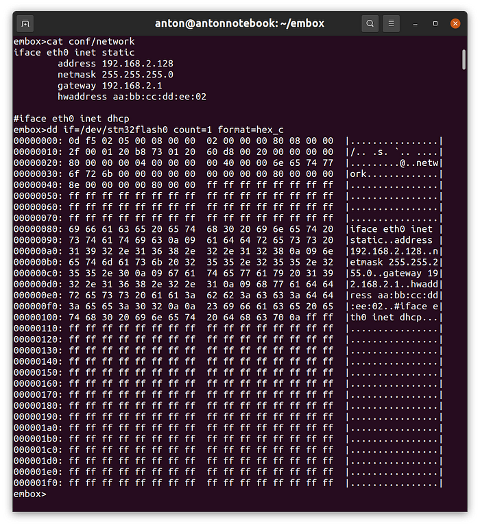
This screenshot shows a file with network settings that can be changed during runtime. And also the data of the file system itself is given. You can see both superblock and dentry and since the file is the first you can see the content of the file itself.
The same can be seen directly in the microcontroller’s memory.
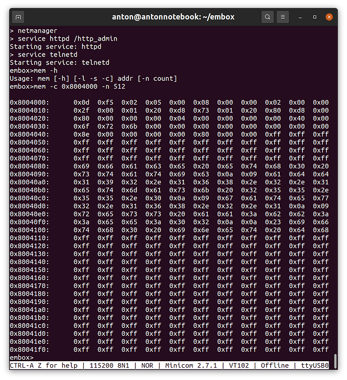
It remains to estimate how many resources are needed. The driver itself is less than a kilobyte, we have almost completely analyzed it. There is no overhead for RAM, or rather, they are included in the overhead of the file system itself. You need to have a superblock and other objects to work with files, but we have already included them to work with initfs. And of course there is a flash driver code, the flash itself and a cache buffer for it. But all this is also necessary when working directly without the file system.
A log-file
With the settings, everything turned out to be not so complicated. Now let’s see how you can organize a log file. The first thing that comes to mind is to select a block and write messages there in a loop. For convenience, you can make messages of the same length and add a message counter. To optimize the number of rewrites, you can use two blocks and erase only once for many records.
To do this, you can create a special file system. But we have the file system, and in fact a log file is just a file that is treated as a ring buffer. Thus, we can develop a library and application that will be independent of the file system format, flash memory and the microcontroller itself. Therefore, it will be much easier to develop than a new file system driver. You can even take some existing logger, but I still want to add some specifics. Let our file have a limited number of records and the records will be the fixed size.
You can develop and debug application code directly on Linux, but I will do it for Embox and run it in qemu.
The functionality of the application for working with the log file is as follows. You can view the entire log that is written to it. And add a message in text format.
The function of printing a log
The function of record a new message to the log
The application is so easy that it is not necessary to explain it.
The library is a little more complicated, because we need to know where the current pointer is from to write the message and start outputting the file. The simplest thing is to store this pointer at the beginning of the file. But then we will have to rewrite it every time we enter the next message, but since our file system is designed for flash it is not very good.
Let’s add a marker to the beginning of each record. It is enough to have only two states, then when scanning the file, we can determine the required index of the message log by changing the marker. And let’s add a message number for readability. Also we can restrict the number of records to 256, that is, we need two bytes.
Thus, the format of our recording will be
<marker><index>:”message”<whitespases>’\n’The function of record a new message
The function of reading the log
The function to search the index of a last written message
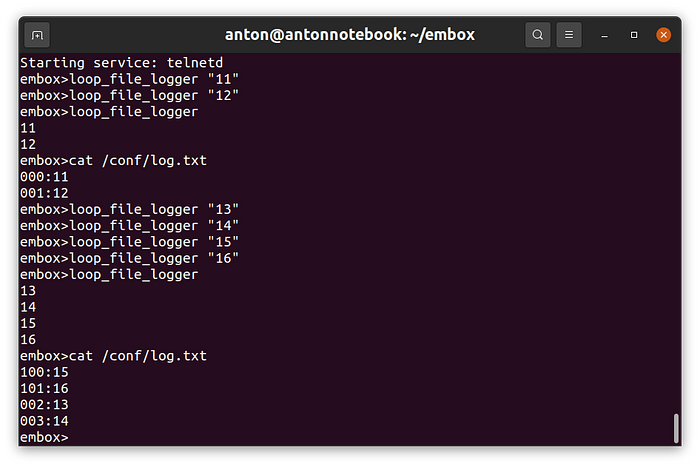
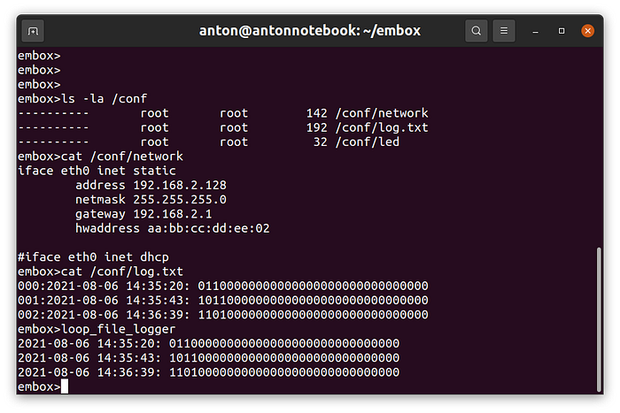
The results is good seen on the screenshot:
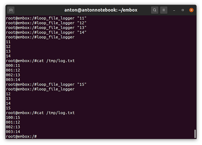
after adding our logger into a configuration for STM32F4-Discovery we got the same result:
Simple device
The file system is certainly good, but let’s try to apply it on some simple device.
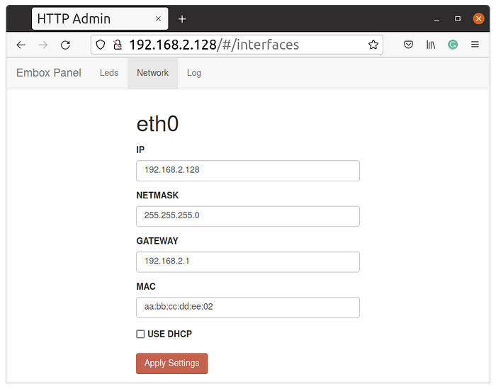
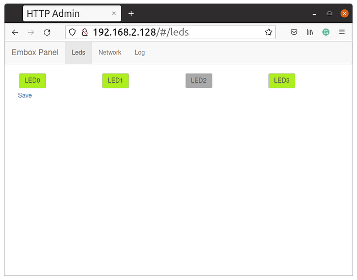
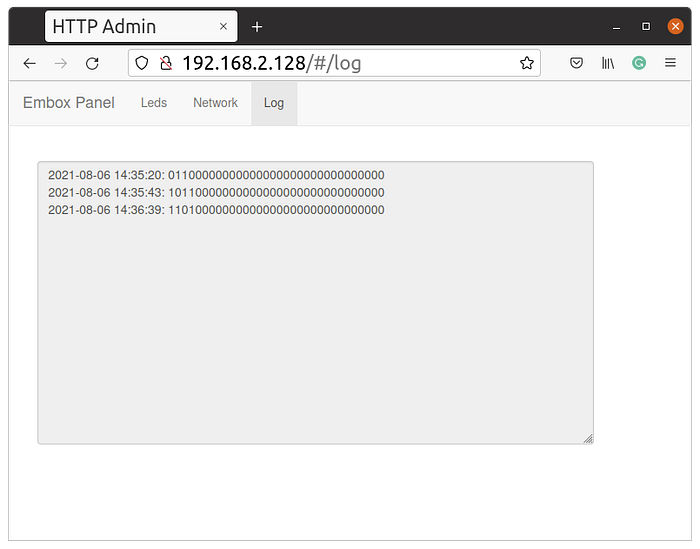
Let’s a little improve the device described in the article “Add modbus to Embox RTOS and use it on STM32 and not only on them”. Let me remind you that this is a network device that allows you to control LEDs remotely via a web interface or via Modbus TCP. Let’s add the ability to change the network setting and a logger that will record the state of the LEDs at the time of their change. The format of the message will be very simple: “time: LED states”
There is nothing even to describe here. Add the appropriate pages and java script as described in the article “Design web-site on Linux and running on a STM32 MCU“. Our logger already knows how to display messages in text format, which is essentially enough to use it in CGI scripts. You just need to use wrapper.
It is enough, now I just give screenshots, in which, in my opinion, everything is clear.
Conclusion
In the article we have shown that it takes some resources to use the file system. However the overhead is not that big. If you need to store just 16 bytes of settings, then a couple KB are redundant. On the other hand, most modern devices already have a web interface or another interface for remote control, therefore we need some resources anyway.
Also, it should be taken into account that flash memory has a block structure, therefore, if we want to store changeable settings inside the microcontroller, we need to allocate at least one block. For f4 it is 16 kB.
If the device has an SD card and you need to be able to read FAT, then in this case, adding the file system for settings and logging definitely makes sense, since we get the convenience and versatility of the solution for an modest overhead. For example, the DumbFS described in the article works on the STM32 series (f3, f4, f7, h7), while others simply have not tried it. And the logger given in the article generally works on any file system.
You can see how it works in this short video
Everything describing in the article you can reproduce yourself with Embox.
